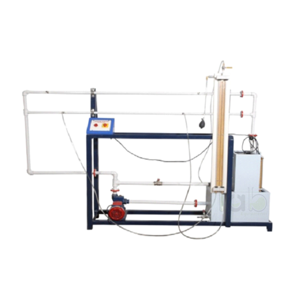
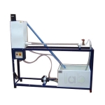
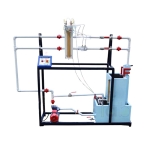
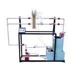
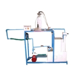
Quick Answer: Friction In Pile Lines Apparatus measures the head loss due to friction in pipes and the friction factor for the Darcy-Weisbach equation, using two GI pipes of ½" and 1" diameter connected in parallel over a 1 m test section.
Last updated: October 2026
Key Features
Two GI pipes, ½" and 1" diameter, in parallel
Pipe test section length 1 m
Pressure tappings on each pipe with a differential manometer
Control valve on each pipe so one pipe is used at a time
Stainless steel sump tank of 50 litres, FHP pump, flow control and by-pass valves
Measuring tank of 25 litres with piezometer; mechanical/electronic stop watch
Technical Specifications
Specification
Value
Pipes
2 Nos., GI, ½" and 1" diameter
Pipe test section
Length 1 m
Water circulation
FHP pump
Flow measurement
Measuring tank with piezometer, 25 litres
Sump tank
Stainless steel, 50 litres
Stop watch
Mechanical / electronic
Control panel
On/off switch, mains indicator
Electricity
Single phase, 220 VAC, 0.5 kW
About This Product
With one pipe opened at a time, students set a flow rate with the control and by-pass valves, read the pressure drop across the 1 m test section on the differential manometer and time the measuring tank. Repeating this for both diameters gives the friction losses and the friction factor for the Darcy-Weisbach equation. Pipe-friction practicals in the FLUID MECHANICS LAB run on this self-contained unit, engineering lab equipment in India that re-circulates water from its own stainless steel sump tank.
Frequently Asked Questions
Q1. What pipe sizes are fitted? Two GI pipes of ½" and 1" diameter, connected in parallel, with a test section length of 1 m.
Q2. Can both pipes be tested at once? No. Control valves on each pipe allow one pipe to be used at a time for the experiment.