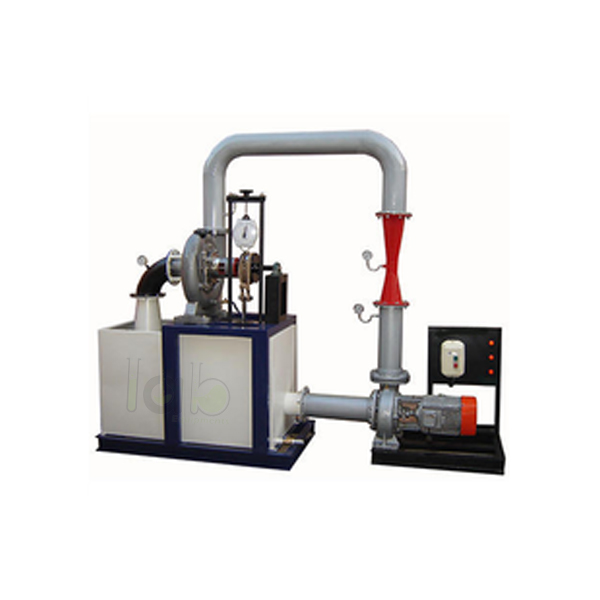
Quick Answer: Kaplan Turbine Test Setup is an axial flow reaction turbine rig for low heads, used to study turbine operation and determine output power and efficiency. It is offered in 1.33 HP and 5 HP versions, each with a scroll casing, guide vanes, a runner with adjustable vanes and a draught tube.
Last updated: October 2026
Key Features
Scroll casing housing a runner with hub and airfoil vanes
Water enters through stationary guide vanes and passes axially through the runner
Transparent acrylic cylinder between draught tube and casing to watch flow onto the vanes
SS shaft with brake arrangement; runner assembly on a thick cast iron pedestal
Pressure and vacuum gauges at inlet and outlet for the total supply head
Control panel with star/delta starter, mains indicator and MCB for overload protection
Technical Specifications
Specification
1.33 HP version
5 HP version
Output power
1.33 HP / 1 kW
5 HP / 3.75 kW
Discharge
1500 LPM (approx.)
5000 LPM (approx.)
Supply head
5 m
5 m
Rope brake dynamometer
Dia 200 mm
Dia 300 mm
Sump tank
300 litres
600 litres
Circulation pump
7 HP, three phase
20 HP, three phase
Speed
1500 RPM (approx.)
1500 RPM (approx.)
Runner
Adjustable curved vanes
Adjustable curved vanes
Discharge measurement
Pitot tube with manometer
Pitot tube with manometer
Electricity
15 kW, 440 V AC, three phase
15 kW, 440 V AC, three phase
About This Product
Because the power produced is proportional to QH, a low-head turbine like this needs a larger discharge to give the same power, which the HYDRAULIC MACHINE LAB set-up supplies from its centrifugal pump. Loading the runner through the brake arrangement and reading the inlet and outlet gauges gives the data for output power and turbine efficiency.
Frequently Asked Questions
Q1. Where can the flow onto the vanes be seen? Through a transparent hollow acrylic cylinder fitted between the draught tube and the casing.
Q2. What head does the turbine work at? It is suited to low heads; both versions are listed with a supply head of 5 m.



.jpg)


