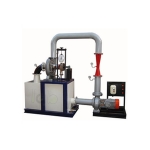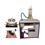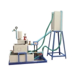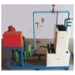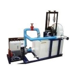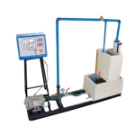
Pelton Wheel Turbine Test Setup
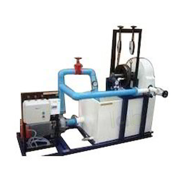
Product Code : EL-HML-11050
Quick Answer: Pelton Wheel Turbine Test Setup is a tangential flow impulse turbine rig for studying turbine operation and determining output power and efficiency. It is offered in 1.33 HP, 2 HP and 5 HP output versions, with a brass bucket-type runner, spear-controlled nozzle and rope brake dynamometer.
Last updated: October 2026
Key Features
- Tangential flow impulse turbine: water strikes the buckets along the tangent of the runner
- Nozzle and spear in stainless steel/mild steel; spear set by hand wheel to regulate flow
- Transparent acrylic window in the casing for watching flow onto the buckets
- Rope brake dynamometer on the SS shaft for loading; pressure gauge at the inlet
- Runner assembly on a rigid MS structure; speed 1000 RPM (approx.)
- Control panel with star/delta starter, mains indicator and MCB for overload protection
Technical Specifications
| Specification | 1.33 HP version | 2 HP version | 5 HP version |
|---|---|---|---|
| Output power | 1.33 HP / 1 kW | 2 HP / 1.5 kW | 5 HP / 3.75 kW |
| Discharge | 300 LPM (approx.) | 400 LPM (approx.) | 630 LPM (approx.) |
| Supply head | 25 m | 40 m | 45 m |
| Rope brake dynamometer | Dia 200 mm | Dia 200 mm | Dia 300 mm |
| Sump tank | 150 litres | 200 litres | 300 litres |
| Circulation pump | 5 HP, three phase | 7.5 HP, three phase | 15 HP, three phase |
| Speed | 1000 RPM (approx.) | 1000 RPM (approx.) | 1000 RPM (approx.) |
| Impeller (runner) | Brass, bucket type | Brass, bucket type | Brass, bucket type |
| Discharge measurement | Pitot tube with manometer | Pitot tube with manometer | Pitot tube with manometer |
| Electricity | 15 kW, 440 V AC, three phase | 15 kW, 440 V AC, three phase | 15 kW, 440 V AC, three phase |
About This Product
Water from the centrifugal pump reaches the runner through the nozzle, and only kinetic energy is available at the turbine inlet, which suits this turbine to high heads. Students load the runner with the rope brake dynamometer and read the inlet pressure gauge for the total supply head, then calculate output power and efficiency in the HYDRAULIC MACHINE LAB.
Frequently Asked Questions
Q1. How is the flow into the turbine regulated?
By adjusting the position of the spear in the nozzle with the hand wheel provided.
Q2. How is the supply head measured?
A pressure gauge fitted at the turbine inlet measures the total supply head to the turbine.
Q3. What power supply does the set-up need?
Electricity of 15 kW, 440 V AC, three phase, along with a water supply and drain.
For a quotation on the Pelton Wheel Turbine Test Setup, contact Lab Equipments Ambala.
.jpg)